 |
| March 11, 2014 | Volume 10 Issue 10 |
Designfax weekly eMagazine

Archives
Partners
Manufacturing Center
Product Spotlight
Modern Applications News
Metalworking Ideas For
Today's Job Shops
Tooling and Production
Strategies for large
metalworking plants
Engineer's Toolbox:
Designing for larger injection-molded parts
By Gus Breiland, Customer Service Engineer Manager, Proto Labs
Design elements on larger parts must work together in a delicate dance where balance between size, geometry, and material type is critical. Larger parts tend to be thicker. Thicker walls tend to flow better. But thicker walls may also create more opportunity for overly thick geometry, causing risk to cosmetics and structural integrity.
Larger parts also flow farther from the gate, so resin is colder at the end of fill. Good design practices such as uniform wall thickness, draft, and radii help flow resin farther with less internal stress caused by sharp twists and turns. The farther you let resin wander, the harder it is to control its behavior.
Let's start with size. The maximum part outline that can be molded at Protomold is approximately 18.9 in. by 29.6 in. (480 mm by 751 mm) with a maximum part volume of approximately 59 cu. in. (967 cc.). As part depth increases, maximum part outline decreases at a rate of approximately 2 in. (50.8 mm) in both length and width per 1 in. (25.4 mm) of depth, for example:
- 16.9 in. by 27.6 in. at 1 in. deep (429 mm by 701 mm at 25 mm);
- 14.9 in. by 25.6 in. at 2 in. deep (378 mm by 650 mm at 50 mm);
- 12.9 in. by 23.6 in. at 3 in. deep (327 mm by 599 mm at 76 mm);
- 10.9 in. by 21.6 in. at 4 in. deep (277 mm by 549 mm at 101 mm).
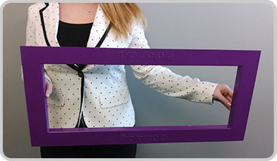
An injection-molded ABS part with an outline of 13.5 in. by 29.5 in. by 1.2 in. provides actual perspective on Protomold's size capabilities.
Part depth cannot exceed 4 in. (101 mm) from the parting line (with 3 degrees of draft), or 8 in. (202 mm) total, if the parting line can pass through the middle of the part, inside and outside. Another way of looking at this is a 4-in. (101-mm) cup, or an 8-in. (202-mm) capital "H." The outlines noted are pre-shrink, so with higher-shrink resins, maximum part outline will decrease. Adding side-actions will also decrease the outline.
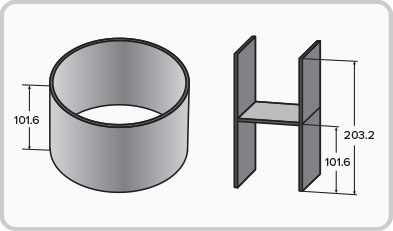
Maximum part depth is 101.6 mm from the parting line, or 203.2 mm total, and requires draft and/or thick walls. A parting line also needs to be at one edge of the part.
Draft is important on all parts, but the larger and deeper the part is, the more significant draft on side walls, ribs, and posts becomes in the facilitation of part ejection from the mold. Protomold requires approximately 1 degree of draft per inch of depth from the parting line. Minimum draft, regardless of depth, is a half degree. If you have a 3- to 4-in.-deep part, start with 2 degrees of draft per side and upload your file for review. Protomold will guide you if additional draft is needed.
Wall thickness is another element that plays a crucial role in improving the quality of larger, heavier parts. When wall thickness is uniform, the part is able to cool uniformly. This allows the part to shrink equally across its geometry. Sections that vary in thickness take different lengths of time to cool, which can result in warp. Recommended wall thickness varies by material, but larger parts should have thicker walls, often at or near the manufacturer's maximum recommended thickness for a specific material. However, try to avoid designing wall thicknesses greater than 0.150 in. (3.8 mm) as most resins start to sink on themselves without special process assistance. Gussets can also be built into unsupported walls to provide further strength.
Plastic flows around curved edges much better than sharp ones, so radii should be incorporated into the design of 90-degree angles to improve the flow of material. Identifying the right radius will also help strengthen the part by reducing stress concentrations. But, if a radius is too big, sink can occur on the outside of the part.
With all part sizes, the type of material that is used is always an integral part of a balanced design. Tough-flowing materials, like polycarbonates and glass-filled nylons, may require adjustments in geometry or additional gates to prevent short shots or reduce fill pressure. If filling a larger part is a concern, our free ProtoFlow analysis can identify troublesome areas so modifications can be made.
When your 3D CAD model is uploaded, our quoting system will show additional design considerations such as ejector pin and gate placement layouts, which can affect cosmetic appearance, material distribution, and more. And if your part exceeds the maximum outline, there are possible solutions (like splitting the part in half) that may solve that issue.
We encourage contacting a Customer Service Engineer at customerservice@protolabs.com or 877.479.3680 to help you find that right balance of size, geometry, and materials -- and so you get the best part possible as fast as possible.
Read past Protomold Design Tips here.
Want more information? Click below.
Published March 2014
Rate this article
View our terms of use and privacy policy